Hacking a BMW car radio
05 May 2026I have my hands on an old BMW car radio. This is one of the old radios where you need a 4 digit code to get it working again after unplugging the power. This code is missing. I’ll attempt to get the code from the radio. It will involve some hardware hacking.
This is the thing. Standard radio dimensions. According to the web “one of the best sounding radios of the 90s.” It is supposed to go into a nice old BMW convertible. The code was lost during several past transactions. Also, attempts to get the code via online services failed.
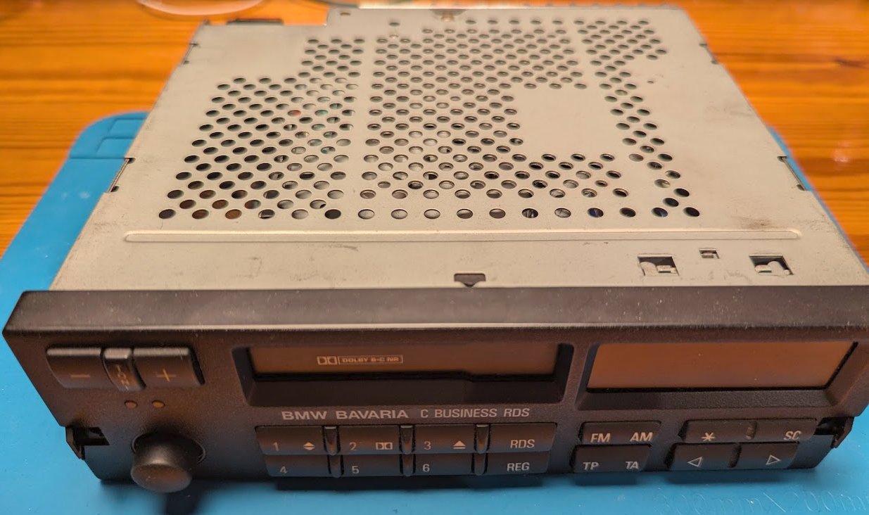
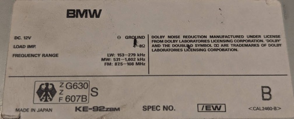
The type of the radio is KE-92 ZBM. It says “BMW”, but the manufacturer is Pioneer. It is made in Japan.
Let’s do some research. I found the service manual on the archive.
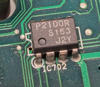
The system controller IC is connected to a 64 bit fuse ROM. The type of the ROM is P-2100R. This DIP-8 part from Seiko is also regularly referenced on web pages where people look for missing radio codes. This ROM should contain the missing code.
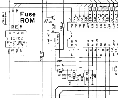
The datasheet for the part is available here
Let’s open her up:
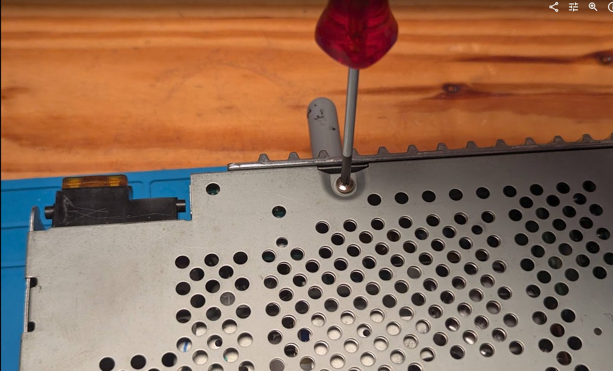
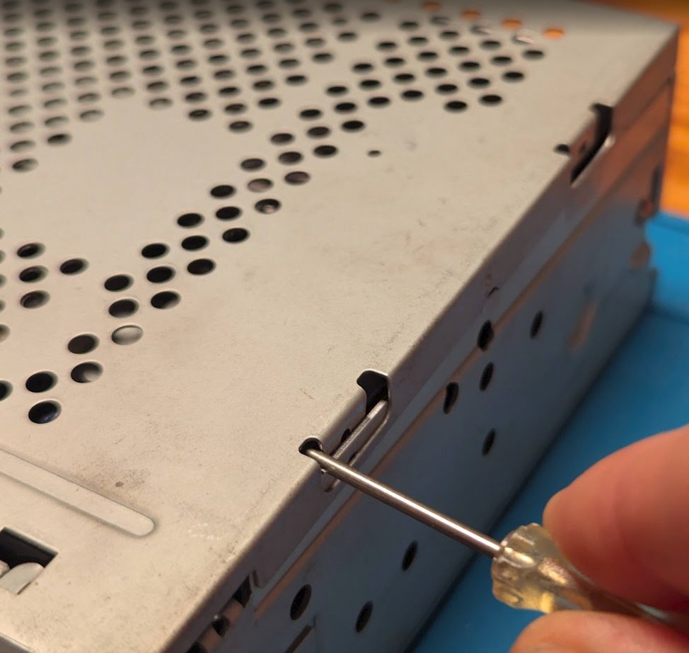
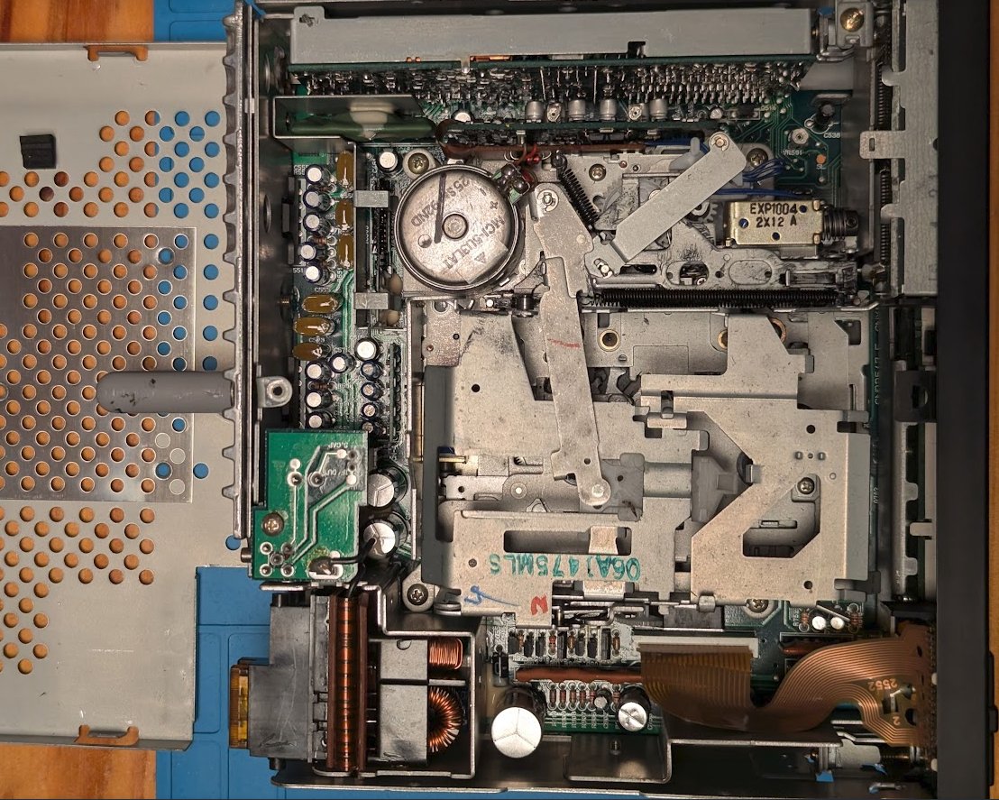
The top is removed, giving a nice view of mostly the cassette drive (center). Power electronics and interface to the front panel on the bottom. Tuner board on the top. Amplifier on the right.
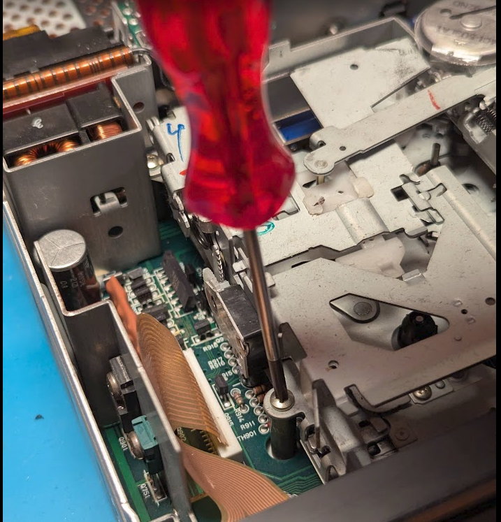
Let’s remove the cassette deck to access to the main PCB with the system controller and the target ROM IC.
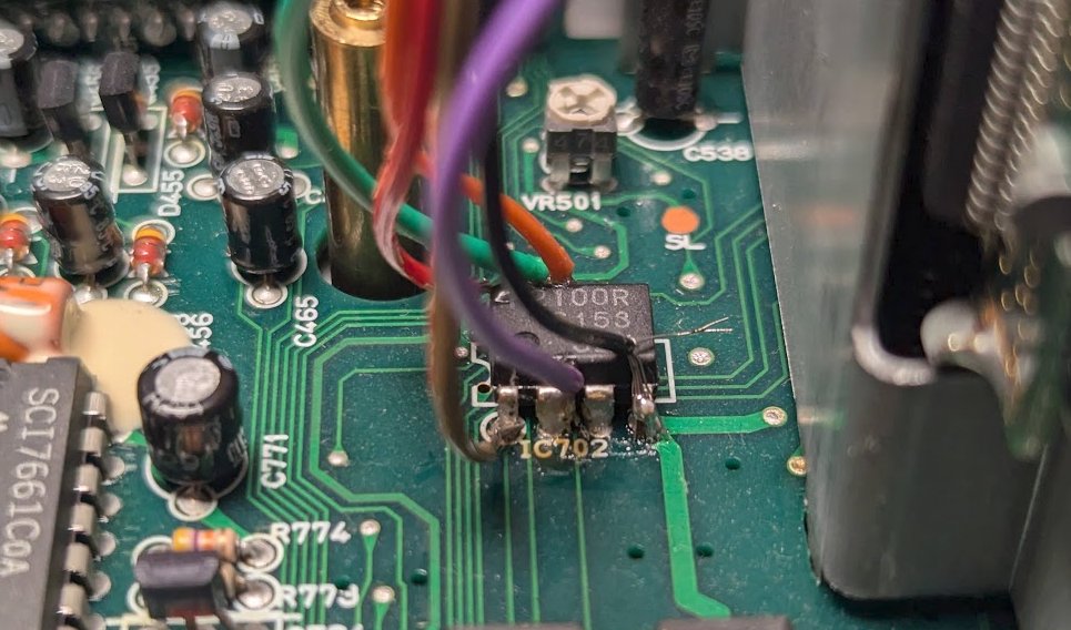
Cassette deck removed. Free access to the system controller (bottom center) and the Fuse ROM P2100R (or S2100) next to it on the right. DIP-8 package.
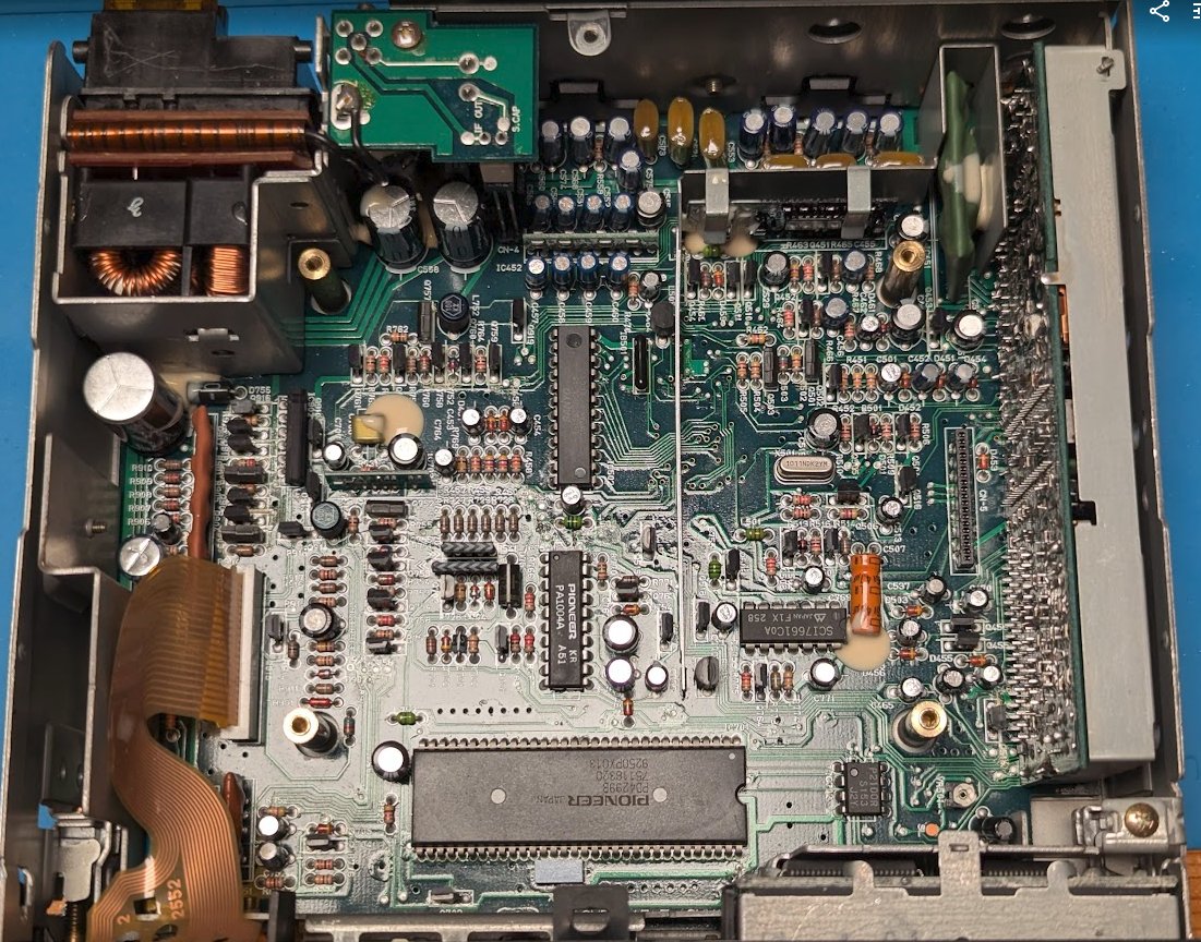
Note, that all major chips say “Pioneer”. No BMW branding to be seen. It only says BMW on the outside.
Target acquired. Since the part is not socketed, but soldered, I’ll attempt to solder on jumper wires with the part in place.
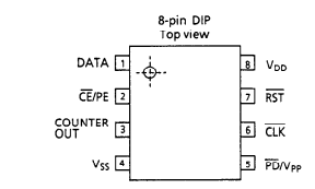
Where are the signals? The datasheet gives this pinout for the S2100 part. So, we’ll need a clock at least and look at the data. VDD is from 1.1 to 5.5 V. VSS is GND. My idea is to use a Raspberry Pico to handle the dump from the DATA pin.
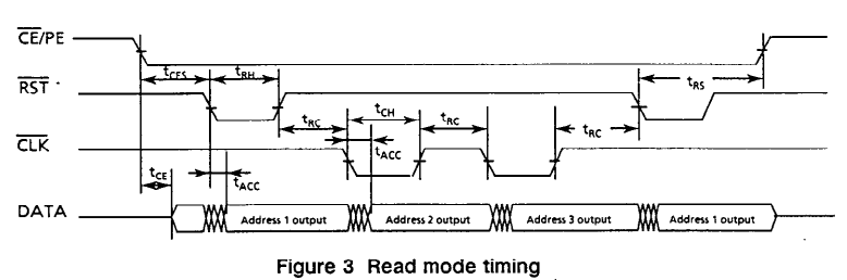
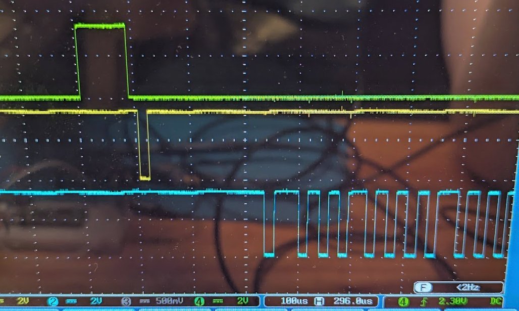
Read timing from the datasheet CE/PE needs to be held low. A negative pulse on RST latches the first bit on DATA. Pulses on CLK then yield the other 63 bits.
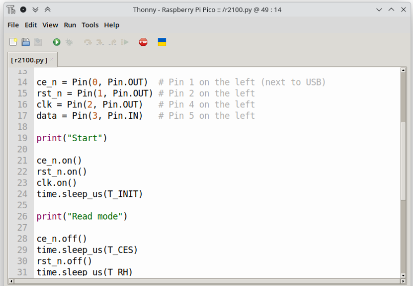
This and a few lines of Micropython should be able to get it done.
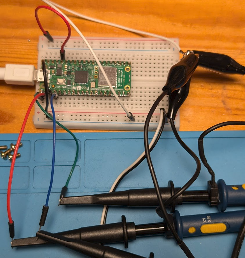
I’m using Thonny here. Quick and dirty.
Verify the waveform on the scope. It looks somewhat like what the datasheet requests. Now, soldering.
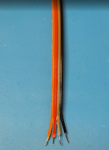
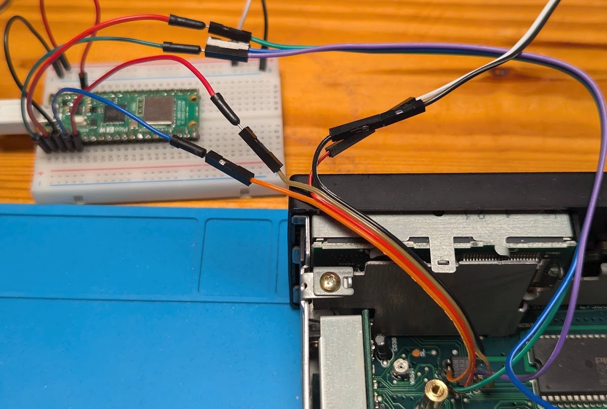
It was a bit of a tight space, but manageable. All wires attached. I was first hoping to get away with leaving out the RST or CE/PE signals, but nope. Also yes, test clips exist, but not in my drawer (yet).
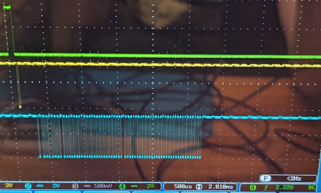
Let’s go! We’ll see, if the simple script is enough to get the data out of the chip.
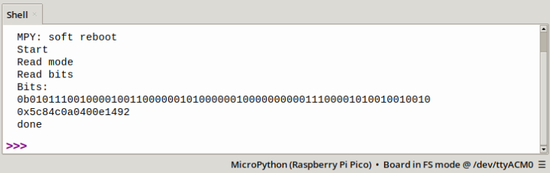
One-shot! Got the full dump on the first try. Timing was obviously fine (enough). 0x5c84c0a0400e1492. Now, how does one get the code from this dump?
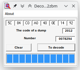
I found some old Windows tools that are supposed to do the right thing and extract the radio code from a ROM dump. Tried the first one and it seemed to work.
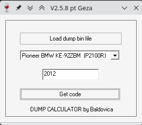
Now the second one did not work so easily. I had to write the code to a bin file first.
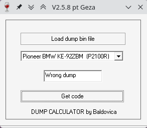
When the bit order is reversed, also the second tool gives the same code. This looks like a success! One question remains: How do these tools extract the code (and serial number) from the dump?
Let’s jump into ghidra and take a look. I give the first tool a try first, because that one also decodes the serial number. Ghidra does not get very far, because the thing is seemingly Visual Basic, compiled to MSIL (intermediate language).
Actually the intermediate language is not MSIL, but the older P-Code. Using VB Decompiler Lite to look into the file. In the “btDecode_Click” function I find a lookup table (0->15, 1->7, 2->3, …):
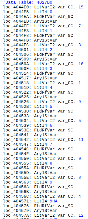
Then, further down, there’s a check that the first byte is 0x50.
Otherwise prints “Error” in the result field. Then follows an unrolled loop 4 times, presumably extracting the 4 digits of the code. Then comes the section that decodes the serial number.
Looking at the P-Code makes my eyes hurt, so I just tried using the lookup table on the last few bytes of the memory dump and that yielded the correct serial number.
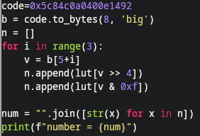
This works and gives the correct serial number (same as written/stamped on the radio). Now, let’s take a look at the second tool.
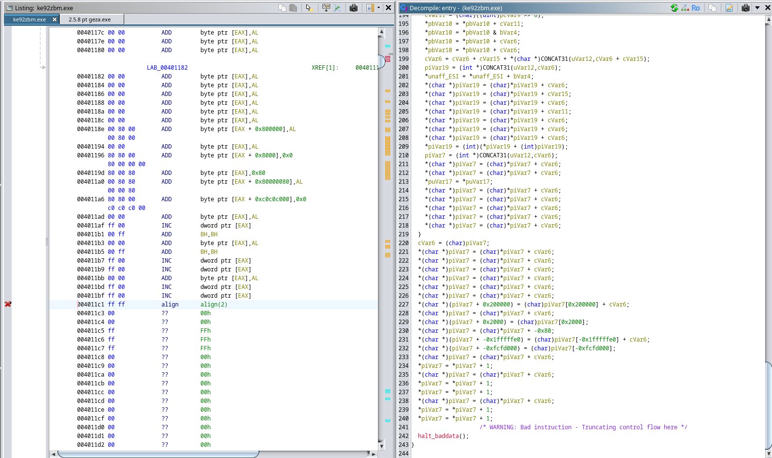
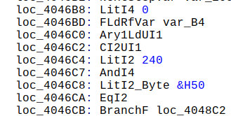
Ghidra does a better job here, since no VB involved. I can find a function that writes into the GUI with SetDlgItemTextA(). Either “Wrong dump”, which I’ve seen before or some decoded result. Some vars are already named below:
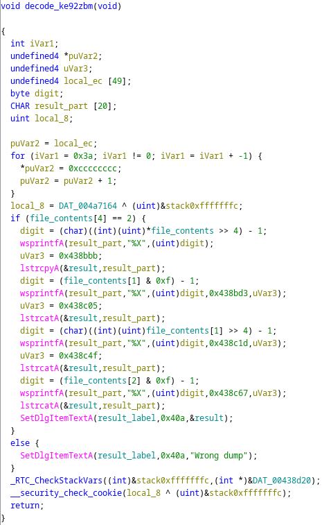
So, two ways to confirm the code from the dump. Algorithm for decoding serial number and radio code extracted. One thing remains. The decoder tool also came with some assembly code that I first thought would reveal the algorithm. But no! …
That code turned out to be driving the LPT port on an older PC to perform the memory dump! These were the times when one had direct access to the hardware pins from the CPU. Today, I can wiggle pins inefficiently with some lines of python.
Follow me on X and github for more random hardware shenanigans.